Midterm Revision
CS180
MIDTERM REVISION YEEEEEEEEEE BOIIII
copyright chaw-ca-leepz jk i know nothings

Von Neumann Model
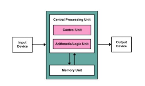
Computers consist of 5 parts:
1. CA (Central Arithmetic Unit)
2. CC (Central Control Unit)
3. M (Memory)
4. I (Input)
5. O (Output)
Fetch -> Decode -> Execute -> Writeback -> Check For Interrupt Flag -> (back to) Fetch
In the Fetch stage, the instructions are fetched from memory (using the program counter, which is a register that contains the address of the instruction) into the CPU (and into the instruction register).
In the Decode stage, the instruction is sent to the instruction decoder.
In the Execute stage, the ALU is used to do actual computation.
In the Writeback stage, the result of the execution may be written back to registers or memory
Loaders
Loaders are used to load programs.
- Able to read the executable format
- Copy the text and data segments into the correct memory addresses.
- Allocate space for Stack and Heap for the new running program
→ Remember, heap is for dynamic, stack is for static
- Set the program counter value to the address of the starting instruction of the loaded program.
- The newly loaded program runs.
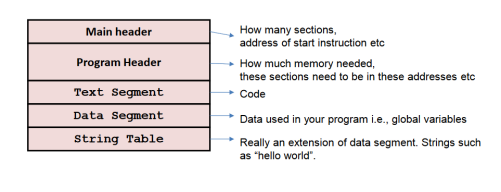
Layout of an Executable
Boot-Up Process
/Boot Sequence
1. Power-On (Hardware up and running)
2. Run BIOS (Basic I/O System)
◇ BIOS is a chip that can be found on the mother board.
◇ It is separate from the CPU and RAM
◇ BIOS is actually accessed via a hard-coded address, which indicates the starting of the BIOS. The BIOS is stored in flash memory, in ROM (read only memory).
◇ Search through the secondary storages (ie hard disks for bootable drive)
3. BIOS load and run a power-on self-test (POST) to check if the BIOS is uncorrupted, then checks for each hardware peripheral and initializes them then loads and runs the Master Boot Record
◇ The Master Boot Record (MBR) is the information in the first sector of any hard disk or diskette that identifies how and where an operating system is located so that it can be boot (loaded) into the computer's main storage or random access memory.
◇ The MBR holds the information on how the logical partitions, containing file systems, are organized on that medium. The MBR also contains executable code to function as a loader for the installed operating system—usually by passing control over to the loader's second stage, or in conjunction with each partition's volume boot record (VBR). This MBR code is usually referred to as a boot loader.
◇ Small 512 bytes (may be different, not sure)
◇ Any bootable media - SSDs, USBs, CD-ROMs - have MBRs
4. MBR may load boot loaders (chain-loading) for different OSs.
5. Load and run OS
CPU - I/O communication
From CPU to I/O //CPU taking initiative
- Special Instructions
- Memory-mapped I/O
→ Device (I/O) registers are given hard coded explicit addresses for CPU to read/write
→ The graphics and memory controller hub (GMCH) hub is used to decide between the main memory and the I/O devices, to a human the memory addresses of an I/O device and main memory are indistinguishable
From I/O to CPU //I/O taking initiative
- Polling
→ Processor continuously checks I/O device to see if it is ready for data.
→ while(*(0x13AF384) != DONE);
→ OR while(done_bit==0) (done_bit is volatile and may be changed at anytime and is not changed by the CPU)
→ FASTER RESPONSE TIME but WORSE/LOW CPU UTILiZATION
- Interrupt
→ CPU gets interrupted BY the I/O
→ Processor can be doing other tasks while waiting for last data transfer to complete - very efficient.
→ (sort of like event-based messaging)
→ Interrupt Signal gets set to 1 (interrupt) (0 is no interrupt), Interrupt Flag gets set to which type of device or interrupt it is and one of the bits on it is set to 1 and Interrupt Vector tells what is interrupting
→ Two types of interrupts
⇒ Non maskable (cannot ignore)
⇒ Maskable (can ignore)
→ SLOWER RESPONSE TIME but BETTER/HIGH CPU UTILIZATION
Interrupt Handling
Steps
1. Interrupt Flag is set to 1 (0, obviously, means that there's no interrupt)
2. Interrupt Vector gets set to a number, lets call this N
3. Depending on what's in the Interrupt Descriptor Table Register, we are then directed to the Interrupt Vector Table (IVT) (In real mode) or the Interrupt Descriptor Table (IDT) (In protected mode, it's in virtual memory)
4. We then get the Instruction Service Register from the IVT or IDT (ISR is Base Address (which is hard coded during real mode) + 4 * N (4 being the size of the pointer) (4 is for 32 bit, 8 for 64 bit))
Types of Interrupts
3 kinds of interrupts
- Exceptions/Faults (such as i=5/0)
→ Note: f=5.0f/0.0f; does not produce an error - floating point has a representation for infinity.
- Hardware Interrupt
→ I/O
→ For example, pressing a key on the keyboard or moving the mouse triggers hardware interrupts that cause the processor to read the keystroke or mouse position.
- Software-Generated Interrupt
→ System Calls
⇒ For example, accessing a hard disk drive.
Maskable and non-maskable
- Maskable means turned-off (Turned off means allow the CPU to ignore it and handle it later on or not at all)
- Usually exceptions/faults are not maskable
Interrupt priority
- Interrupt handling can be interrupted by higher priority interrupts. (Can only happen if the thing interrupting is maskable)
- Priority number is different from vector number (which shows what kinda interrupt it is)
→ Higher number in priority number( or lower number ) does not necessarily mean higher priority
Direct Memory Access
- Allows devices to read/write memory directly without CPU intervention
- Does not mean accessing the memory in the same cycle
→ Whether multiple devices (eg CPU can access the memory at the same time depends on the memory design)
- Allows CPU processing to be in parallel with device to memory communication
→ Reduces number of interrupts
- Used to avoid programmed I/O (one byte at a time) for large data movement
- Requires DMA controller
- Bypasses CPU to transfer data directly between I/O device and memory
- Version that is aware of virtual addresses can be even more efficient (DVMA, take a guess at what the V stands for)
CPU Privilege modes
- Kernel (Supervisor mode) and user mode
- Privilidged instructions
→ eg. change the idtr value
- Other instructions
→ eg. add, sub, etc
- MODES
→ Protected mode
⇒ Kernel vs User (4 levels of privileges) (We are not talking administator permissions) (windows explorer is runnning in user mode)
→ Real mode
⇒ No diff between Kernel and User
Most programs run in user mode but will send interrupts to the CPUs which calls kernel functions
Interrupts cause kernel mode to be run automatically
Virtual memory means that programs cannot have the PC be in ANY address.
System Calls
System calls are calls into kernel mode, typically performed by executing an interrupt
The difference between system calls and function calls is that function calls do not necessarily have to be system calls.
Here is a list of the common ones from Wikipedia (the important ones, in my opinion, are bolded):
~~
Process Control
• load
• execute
• end, abort
• create process (for example, fork on Unix-like systems, or NtCreateProcess in the Windows NT Native API)
• terminate process
• get/set process attributes
• wait for time, wait event, signal event
• allocate, free memory
File management
• create file, delete file
• open, close
• read, write, reposition
• get/set file attributes
Device Management
• request device, release device
• read, write, reposition
• get/set device attributes
• logically attach or detach devices
Information Maintenance
• get/set time or date
• get/set system data
• get/set process, file, or device attributes
Communication
• create, delete communication connection
• send, receive messages
• transfer status information
• attach or detach remote devices
~~
Kernel Architecture
Different kinds of kernel architecture:
Monolithic: All code in OS runs in kernel mode (More efficient, requires no kernel change, but less stability) (Less stability because everything is talking to each other with kernel mode commands, if one is corrupted then the system's screwed)
Micro Kernel:
- Small part of OS as kernel
- Important services running as processes outside in user mode
- In order for the processes to talk to each other they require system calls (kernel change)
- More stability
Hybrid:
Combination of the above two.
Exo-Kernel: Don't need to know, but has been talked about by MIT for years.
→ Commands can control hardware - risky.
Windows Win95, 98 and ME are monolithic
Windows NT 4.0, 2000, XP and beyond are micro kernel
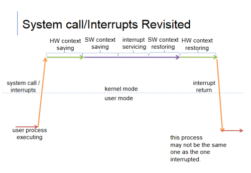
HW/SW context saving (still unclear, tidy up and reconfirm this one)
Context
Consists of user regigisters (FPs, PC, SP)
Status Flags and other special registers
Context saving and restoring
When a program get interrupted, it needs to save its current process and then switch to the ISR, and restore it once the ISR is resolved.
This is call context saving and restoring
Automatic (no instructions involved)
HW saving then SW saving (sometimes HW context saving doesn't save all the registers, for example the FPR)
What happen if CPU don't suppose HW saving?
HW MUST support some kind of saving
It must save at least the PC and SP
It must save them before ISR runs
Where does it save to:
HW reads the SP
Save the registers to the stack
So if the question asks where the hardware saves the context of the running process when an interrupt happens, just say “stack”.
When doing context switching, the values in the Register must be saved before switching, and restore after restoring.
The important registers to save are: PC and Stack Pointer
Other Regs are General Purpose regs, Floating pointer Stack, Status Flag
Context of a process:
The minimum data that must be saved before another code is executed.
The context is saved before switching control to the ISR
Five State Model
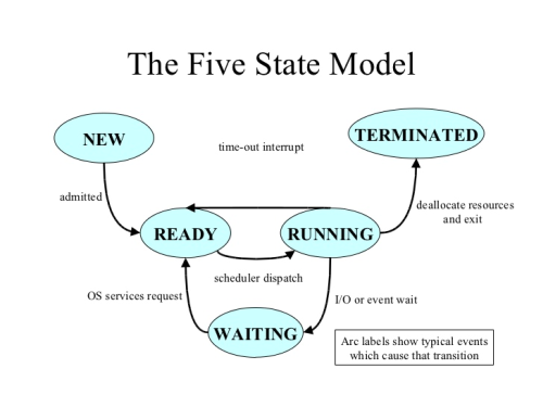
(Think of time-out interrupt as HARDWARE interrupt (such as timer))
(Think of event wait as system call)
Note that these are not real OS states.
For a new state:
- Assign PCB (Process Control Block)
- Assign Process ID (as part of the PCB)
New->Ready: Scheduler decided to schedule P0, but P0 is in the NEW state. Next step is to prep the context for P0.
Ready State:
- Context is set up. (User registers (inlcuding FPs, PC, SP), status flags and other special registers)
Ready->Running: When the scheduler schedules the process to be used by the CPU.
Running:
- Using the CPU
Running -> Waiting: System calls
For example, scanf;
scanf->clib->system call-> more calls -> read(I/O)
Then an interrupt happens (pressed enter)
Waiting goes into Ready at the state/context at the point of read
Waiting:
- Doing I/O or certain system calls
Running-> Terminate
- Exception (divide by 0, for example)
- exit system call
- return 0 from main
NOTE: Exception Interrupt will result the program going from running to terminated.
In a terminated state, you only have a process ID and PCB left. The terminated state is for the parent to know how his children died. The operating system is interested in returning the exit status to the parent, which it gets from the PCB. The way this is done is if the exit status is in the PCB and the process is terminated.
This occurs for child processes, where the entry is still needed to allow the parent process to read its child's exit status: once the exit status is read via the wait system call, the zombie's entry is removed from the process table and it is said to be "reaped".
Zombie status is when the process is dead, but the parent has gotten the exit status, then the PCB is removed and the process is dead.
If the parent dies before the child dies, the child gets adopted by the init (root process)
If the parent dies after the child dies, everything is freed and okay
If the parent does not die and does not pick up the child, there's a PCB leak.
If the parent dies and does not pick up the child, it will be picked up by init and the child will be discarded.
Process Control Block
Process is something that has a PCB (Process Control Block) and process ID (which, again, is part of the PCB).
The PCB stores:
- Process ID
- Process state
- Context
→ Saved here during SW context saving
→ PC, SP, GPRs, etc
- CPU scheduling info
→ Sceduling Policy/Priority
- Memory Management Info
- Accounting Info (?????)
- I/O Status
→ Files opened to the process, I/O devices used in the process etc.
Process Creation
Linux:
fork() - creates process
exec() - runs a new program
Windows:
CreateProcess - basically a combination of fork and exec (Takes in 10 arguments, holy shit!)
My personal understanding of fork and exec is quite simple:
- fork duplicates the current process, returning 0 to the child and the child's pid to the parent.
- exec transforms the current process into another
→ There are various flavours, but the easiest way to remember imo is to remember the meaning of the appended letters.
→ REMEMBER THAT ALL THE ARRAYS USED ARE TERMINATED WITH A NULL. SO IS L. (execl("/bin/ls","ls",NULL))
→ Remember also that the letters position indicates the position in the function the variable will be input.
→ l refers to list, which means the arguments are placed into the function itself
→ v refers to vector, which means the arguments are compiled into an array and fed into the function
→ p refers to path, which means the path is taken into account.
→ e refers to environment, which means the environmental variables are compiled into an array and fed into the function (in the form of, eg, “FUCK=SHIT”) without this, the function inherits the environment from its parent.
wait is basically used to, well, wait for the child process to finish running.
The wait() system call suspends execution of the calling process until one of its children terminates. The call wait(&status) is equivalent to: waitpid(-1, &status, 0);
wait(): on success, returns the process ID of the terminated child; on error, -1 is returned.
getpid() returns the process ID of the calling process. (This is
often used by routines that generate unique temporary filenames.)
getppid() returns the process ID of the parent of the calling
process.
The following are the prototypes of the most relevant functions, as well as the required headers:
~~~
pid_t fork(void);
requires unistd.h
int execl(const char *path, const char *arg, ...);
int execlp(const char *file, const char *arg, ...);
int execle(const char *path, const char *arg,
..., char * const envp[]);
int execv(const char *path, char *const argv[]);
int execvp(const char *file, char *const argv[]);
int execvpe(const char *file, char *const argv[],
char *const envp[]);
require unistd.h
pid_t wait(int *status);
pid_t waitpid(pid_t pid, int *status, int options);
requires sys/wait.h
pid_t getpid(void);
pid_t getppid(void);
requires sys/types.h, unistd.h
CreateProcess is a Windows function so it probably doesn't hold as much significance, and it has 10 arguments so nobody's gonna remember that shit.
~~~
NOTES
exec does not change the pid
you can use int to store pid_t