Introduction
Introduction
Operating Systems - Intro, Program Loading, OS History
--------------------
Why do we need to learn about Operating Systems?
• To understand what goes on under the hood
• Large scale design
• Write better code
• Write an Operating System
--------------------
Outline
• Execution of a program
• Boot sequence
• Roles of an OS
• History of OS
--------------------
Recap - Execution of a Program
(Von Neumann Architecture)
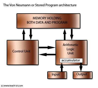
Computers cosist of 5 parts:
1) CA (Central Arithmetic Unit)
2. CC (Central Control Unit)
3. M (Memory)
4. I (Input)
5. O (Output)
The CPU consists of the Control unit and the Arithmetic Logic Unit.
The CPU consists of the Instruction Register, other Registers and Program Counter.
- The instructions are put into the instruction register.
- Program Counter contains the address of the next instruction to be put into the instruction register.
→ The address bus is used by the CPU or a direct memory access (DMA) enabled device to locate the physical address to communicate read/write commands. All address busses are read and written by the CPU or DMA in the form of bits.
→ The instructions are sent to the instruction register by ???
→ The Instruction Register then sends the instructions to the Instruction Decoder
→ Upon decoding the instruction, the Instruction Decoder passes over to the ALU for execution.
→ The result of the execution is then written back to the registers or to memory.
→ The Program Counter increases depending on the instruction size (some architectures use uniform sizes, others (intel) don't) or if there's a jump in instruction (the next instruction is not the one following the current instruction).
How does a program execute?
- Naive answer: load the program into memory and point the PC to the start of the program.
Outstanding questions:
- Where to store the program in memory?
- Which memory address is the 1st instruction of the program?
- How much memory should I reserve for the running program?
- How about stack and heap?
To load the program, we requiree a program called a loader.
- Able to read the executable format
- Copy the text and data segments into the correct memory addresses.
- Allocate space for Stack and Heap for the new running program
→ Remember, heap is for dynamic, stack is for static
- Set the program counter value to the address of the starting instruction of the loaded program.
- The newly loaded program runs.
Memory is used for read and write and for storing the program code.
Input is Keyboard, Mouse, etc
Output is Monitor
Connected by address bus, data bus and control bus.
--------------------
CPU - I/O Communication
CPU does not directly talk to mouse and keyboard,
CPU instead talks to various micro-controllers - USB, eSATA, SATA, PCI, which then talk to mouse and keyboard, etc.
From CPU to I/O (REVISE THESE) //CPU taking initiative
- Special Instructions
- Memory-mapped I/O
→ Device (I/O) registers are given hard coded explicit addresses for CPU to read/write
→ The graphics and memory controller hub (GMCH) hub is used to decide between the main memory and the I/O devices, to a human the memory addresses of an I/O device and main memory are indistinguishable
From I/O to CPU //I/O taking initiative
- Polling
→ Processor continuously checks I/O device to see if it is ready for data.
→ while(*(0x13AF384) != DONE);
→ OR while(done_bit==0) (done_bit is volatile and may be changed at anytime and is not changed by the CPU)
→ FASTER RESPONSE TIME but WORSE/LOW CPU UTILiZATION
- Interrupt
→ CPU gets interrupted BY the I/O
→ Processor can be doing other tasks while waiting for last data transfer to complete - very efficient.
→ (sort of like event-based messaging)
→ Interrupt Signal gets set to 1 (interrupt) (0 is no interrupt), Interrupt Flag gets set to which type of device or interrupt it is and one of the bits on it is set to 1 and Interrupt Vector tells what is interrupting
→ Two types of interrupts
⇒ Non maskable (cannot ignore)
⇒ Maskable (can ignore)
→ SLOWER RESPONSE TIME but BETTER/HIGH CPU UTILiZATION
INTERRUPTION
Two main things; Interrupt flag (to be told which kind of interrupt is ocurring or if there is even an interrupt) and Interrupt Vector ( Parameter to initiate ISR (Interrupt Service Routine))
Only 1 CPU (uniprocessor)
- Processor A is running
- Interrupt X coming in
- Serve Interrupt X
- Qn: What happens to Processor A?
Interrupt Service “Routine”
- Usually has a 1 to 1 mapping with each interrupt vector
3 kinds of interrupts
- Exceptions/Faults (such as i=5/0)
→ Note: f=5.0f/0.0f; does not produce an error - floating point has a representation for infinity.
- Hardware Interrupt
→ I/O
→ For example, pressing a key on the keyboard or moving the mouse triggers hardware interrupts that cause the processor to read the keystroke or mouse position.
- Software-Generated Interrupt
→ System Calls
⇒ For example, accessing a hard disk drive.
Maskable and non-maskable
- Maskable means turned-off (Turned off means allow the CPU to ignore it and handle it later on or not at all)
- Usually exceptions/faults are not maskable
Interrupt priority
- Interrupt handling can be interrupted by higher priority interrupts. (Can only happen if the thing interrupting is maskable)
- Priority number is different from vector number (which shows what kinda interrupt it is)
→ Higher number in priority number( or lower number ) does not necessarily mean higher priority
Interrupts pass the Interrupt Vector (an indice) to an interrupt Vector Table which is made up of function pointers and that's passed to the program counter.
--------------------
How does the CPU transfer control to the correct ISR? (Interrupt Service Routine)
ISRs are functions - to get to the functions for the ISRs we use the interrupt vector table, which holds the pointers to the ISRs
Interrupt Vector Table
- Intel - IDT (Interrupt Descriptor Table)
- Processor has Interrupt Descriptor Table Register
→ Real addressing mode: IVT (can access anywhere in terms of memory)
→ Protected mode: IDT (virtual memory)
Where is the interrupt vector table located?
- Memory
We want to know address containing the starting address of ISR for vector N
- Base Address + 4 * N (4 being the size of the pointer) (4 is for 32 bit, 8 for 64 bit)
How does the HW know where is the base?
- Hardcoded (0x0000 to 0x03ff (0x03fc being the last pointer)) during real mode
- IDTR ( interrupt Descriptor Table Register) (Protected Mode)
--------------------
CPU Privilege modes
- Kernel (Supervisor mode) and user mode
- Privilidged instructions
→ eg. change the idtr value
- Other instructions
→ eg. add, sub, etc
- MODES
→ Protected mode
⇒ Kernel vs User (4 levels of privileges) (We are not talking administator permissions) (windows explorer is runnning in user mode)
→ Real mode
⇒ No diff between Kernel and User
Most programs run in user mode but will send interrupts to the CPUs which calls kernel functions
Interrupts cause kernel mode to be run automatically
Virtual memory means that programs cannot have the PC be in ANY address.
--------------------
Invoking the OS services
int instructions
- Generate the software interrupt (eg int 80h) (h is part of the syntax, indicates hexadecimal)
⇒ mov eax, 4 // ‘write’ system call
⇒ int 80h // calls the kernel
→ in this case 4 is the write system call, 80h is what linux uses for calling the kernel
- x86-64 has a syscall instruction
--------------------
What's the difference between system call and function call?
- System calls cause interrupts, function calls do not
- System calls can use kernel instruction, function calls cannot
- Function calls use the same stack as the user program
--------------------
Different kinds of portability
- Binary portability
- Source code portability
--------------------
CU + ALU -> Model of CPU
Memory = RAM
--------------------
Executable
• A series of instructions
• Instructions are encoded in binary
--------------------
GENERAL NOTES
Control Unit contains a Program Counter (Register) and an Instruction Register
• Program Counter contains the address of the instruction being executed at the current time.
• Instruction Register stores the actual instructions.
Instructions are made up of the following:
• The opcode, which indicates the operator being used
• 2 operands, the registers or memory locations that you would like to perform your operations on. There are two operands, a source and destination.
With instructions are stored in RAM
The instructions are fetched from RAM via a memory controller into the CPU
CPU sends address and control to memory controller and gets data from it.
Memory controller fetches instructions from CPU and data from the RAM and decides whether to read or write to or from I/O
--------------------
Fetch -> Decode -> Execute -> Writeback -> Check For Interrupt Flag -> (back to) Fetch
In the Fetch stage, the instructions are fetched from memory into the CPU.
In the Decode stage, the instruction is being processed. So far, everything is happening from the CU.
In the Execute stage, the ALU is used to do actual computation.
In the Writeback stage, the result of the execution may be written back to registers or memory
The i/o unit essentially encompasses all i/o the computer could possibly do (printing to a monitor, to paper, inputs from a mouse or keyboard, etc.) (From https://www.quora.com/Can-some-one-explain-the-Von-Neumann-architecture)
--------------------